Posts: 1,070
Threads: 115
Joined: Oct 2012
Thanks: 0
Given 0 thank(s) in 0 post(s)
05-10-2013, 06:36 AM
(This post was last modified: 05-10-2013, 06:42 AM by 306Puggy.)
Right, major update time 
Welding guy came back from holiday, so got some welding done for super cheap, had a chat about the project and turbos (not that I know much about them) and waited whilst my stuff got welded nicely.
I didn't think to clean off the protective coating from the exhaust housing which did result in a very bubbly weld, but as long as it does the job of keeping the exhaust gases in I am happy 
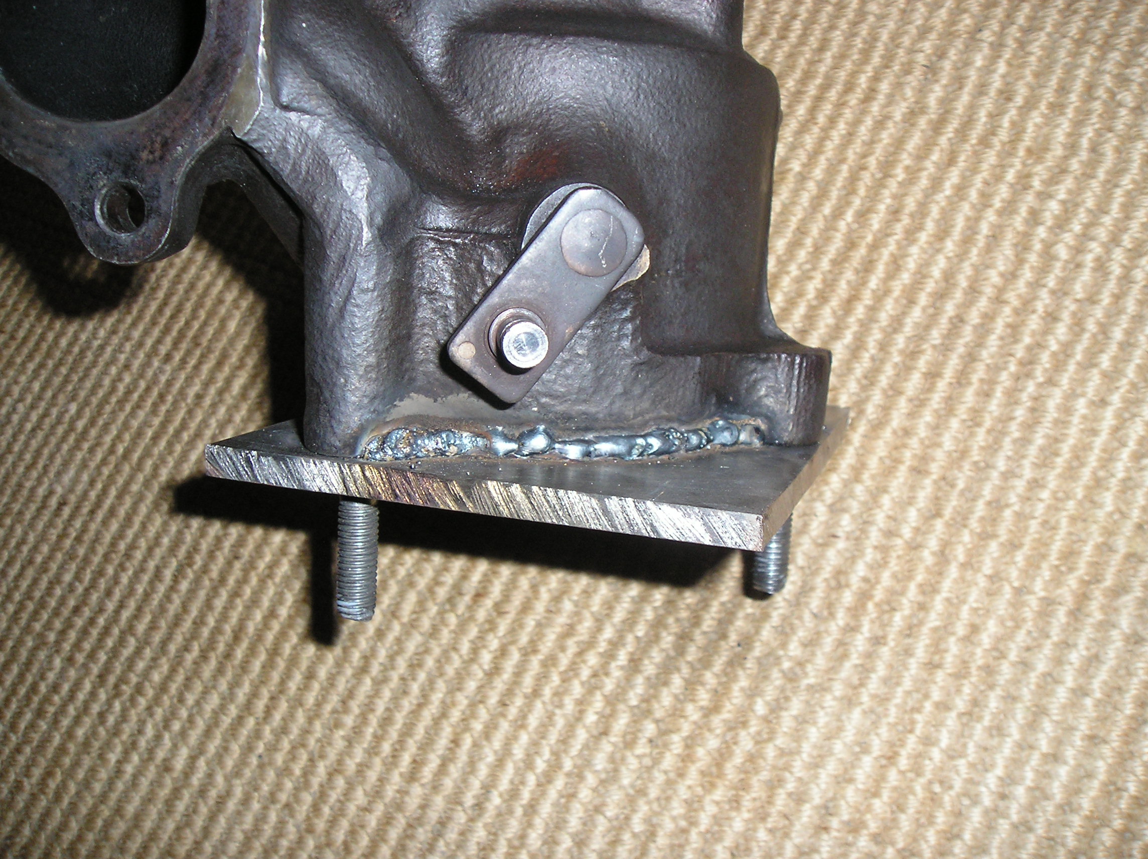
Got the sensor welded in as well, it is really in the path of the gas flow now


Five minutes later I had the turbo back together
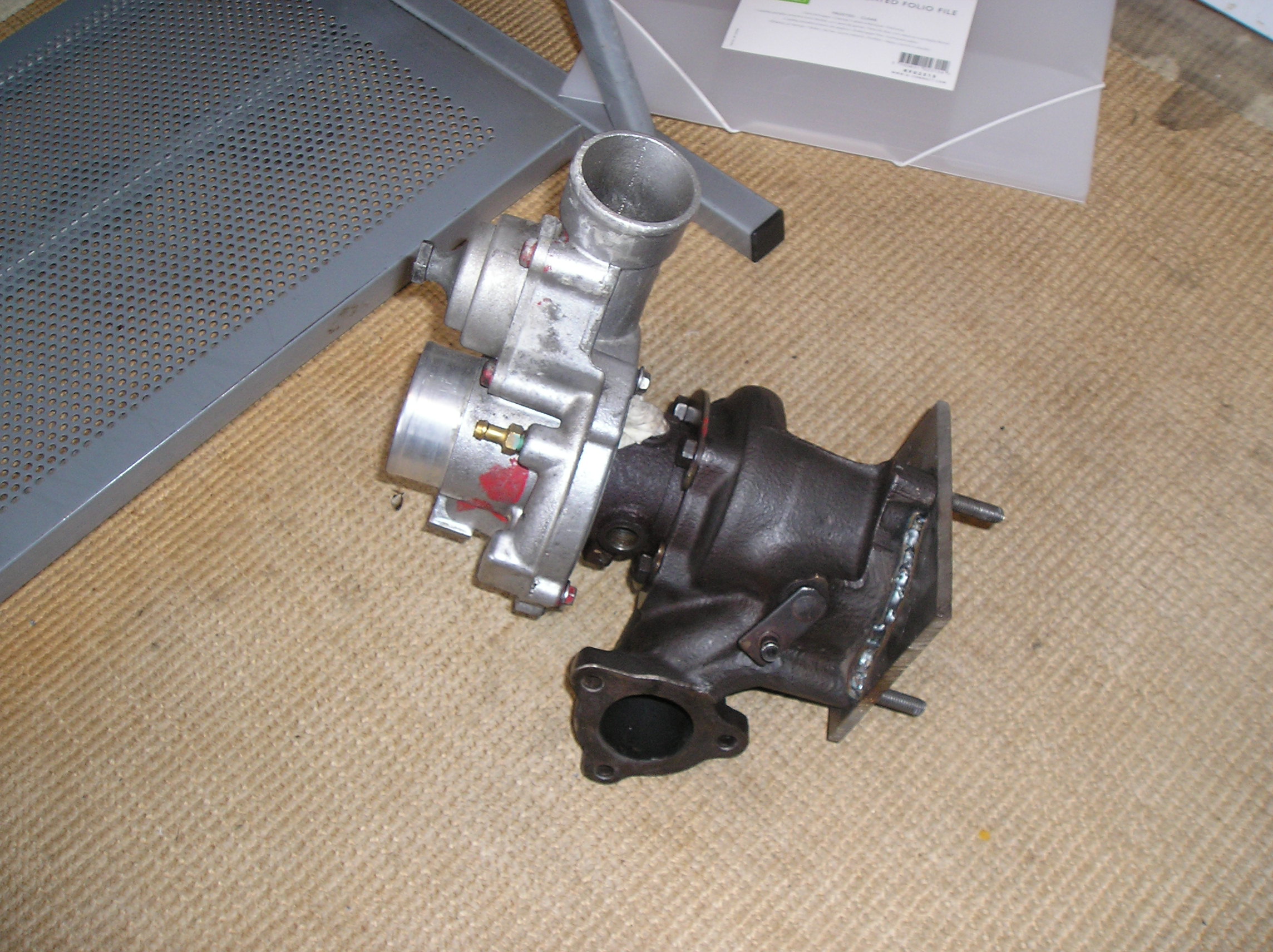
Then I mounted it up to the exhaust manifold

Then I had a look at how I would mount the wastegate actuator
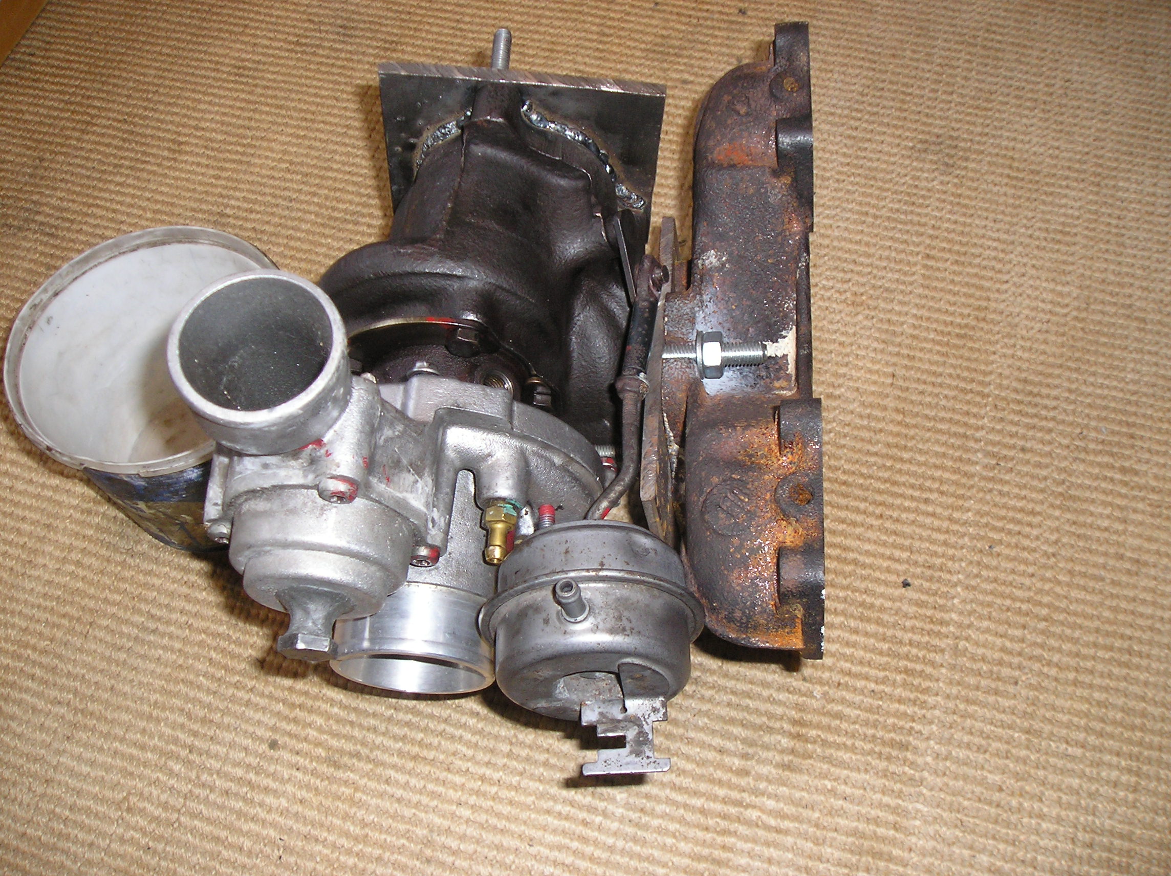

I have no clue, any ideas? Presumably it's got to be able to open the wastegate fully from where it is, not sure how I can even test it (maybe adapt a bicycle pump?) but yeah, no idea at the mo'.
So if anyone has an idea please say...I really want to get this finished. NOW!
Oh yeah and another thing...there is a time limit on this project now, as my mother is having the driveway resurfaced and once that has been done there will be no working on the car anymore 
So I need to get this fitted on and tested before then.
Posts: 4,660
Threads: 343
Joined: Jul 2012
Reputation:
15
Location: Chesterfield
Car Model/Spec: 106 gti / 306 hdi estate
Thanks: 4
Given 3 thank(s) in 3 post(s)
Might just be me but that doesn't look right to me i would have thought the wastegate would have been to the rear of the turbo. Also the cold side will need clocking more as you have to remember the angle of the engine, as it is now the outlet will be pointing at the bulk head.
Im probably wrong about the wastegate but sure some one else will be along to confirm
Posts: 10,864
Threads: 117
Joined: Dec 2011
Reputation:
119
Location: Southampton
Car Model/Spec: 306 HDi and friends
Thanks: 13
Given 106 thank(s) in 106 post(s)
05-10-2013, 07:44 AM
(This post was last modified: 05-10-2013, 07:47 AM by Poodle.)
Almost looks like you've got it mounted upside down tbh, or do xuds actually sit like that..? Turbo needs some clocking, should really be thinking about things like wastegate actuation, comp outlet position, etc long before you start cutting and welding stuff. Trimming the excess off that plate should help.
Posts: 3,662
Threads: 127
Joined: Feb 2012
Reputation:
33
Location: London
Car Model/Spec: ZX Volcane TD
Thanks: 6
Given 32 thank(s) in 32 post(s)
As already mentioned, its going to be a pain in the arse to fit an actuator with the wastegate where it is, especially when you've clocked the cold more, the outlet is going to be right in the way - what a bummer 
Posts: 15,646
Threads: 541
Joined: Dec 2011
Reputation:
124
Location: Aylesbury
Car Model/Spec: 320bhp Impreza WRX
Thanks: 7
Given 59 thank(s) in 58 post(s)
Really liking where your EGT probe is sitting now mate.
For the waste gate actuator id be looking to move it round so it sits above the CHRA or even further, you may find you need a new actuator and maybe use a slightly bent VNT actuator bracket to mount it in the right place.
As for testing it I used a bike pump as I've tested the gauge against a known good boost gauge and its spot on. Have a look at my project thread.
Posts: 1,070
Threads: 115
Joined: Oct 2012
Thanks: 0
Given 0 thank(s) in 0 post(s)
05-10-2013, 02:06 PM
(This post was last modified: 05-10-2013, 02:10 PM by 306Puggy.)
Thanks for the feedback lads 
(05-10-2013, 07:35 AM)Chris_90 Wrote: Might just be me but that doesn't look right to me i would have thought the wastegate would have been to the rear of the turbo. Also the cold side will need clocking more as you have to remember the angle of the engine, as it is now the outlet will be pointing at the bulk head.
Im probably wrong about the wastegate but sure some one else will be along to confirm
The clocking hasn't been done yet, I've just adjusted things roughly so that it is recognisable that it is a turbo. As for the wastegate location that is something specific to this turbo, it would have made sense on the engine it was originally intended for 
(05-10-2013, 07:44 AM)Poodle Wrote: Almost looks like you've got it mounted upside down tbh, or do xuds actually sit like that..? Turbo needs some clocking, should really be thinking about things like wastegate actuation, comp outlet position, etc long before you start cutting and welding stuff. Trimming the excess off that plate should help.
If the turbo was mounted the other way around the exhaust side would be where the compressor side is and the compressor side would be where the exhaust side is  And it would be really low.
As for planning ahead well that is not really my strong point, I find it hard to visualise stuff that way. And would the excess on the adapter plate get in the way? I have already had to do a fair bit of hacksawing and would rather not have to if it is not necessary!
And as I have mentioned, I have not clocked it yet, I'll have to do that when it is on the engine! Should be one of the easy bits!
(05-10-2013, 09:33 AM)Dum-Dum Wrote: Really liking where your EGT probe is sitting now mate.
For the waste gate actuator id be looking to move it round so it sits above the CHRA or even further, you may find you need a new actuator and maybe use a slightly bent VNT actuator bracket to mount it in the right place.
As for testing it I used a bike pump as I've tested the gauge against a known good boost gauge and its spot on. Have a look at my project thread.
Thanks Dum-Dum. I believe that Dave mentioned something about the wastegate but he didn't elaborate, I'll see if I can get his attention.
Fake edit: Just realised I can get a bit of metal welded to the turbo to mani adapter plate to act as a bracket for the wastegate, so that's the problem of what the bracket will attach to sorted 
As for the actuator, can I use any actuator? As I have an actuator on the scrap turbo that I bought by mistake, it is a lot smaller than the one on this turbo!
Fake edit 2:
Okay, found the Dave post:
(28-06-2013, 05:16 PM)Dave Wrote: I might have missed this in the thread previously, but what are you going to do about the actutor and clocking the compressor?, 'cos this is gonna be a major issue even for someone with a welder, a bracket will need to be made, and fitted so it doesnt foul, and where your actuator will then sit, is exactly where your turbo outlet for your intercooler is. You could possibly bend the actuator rod and have it behind the compressor which would work, and then get someone to just simply tack it in place on something steel, this would be the option I would go for.
Hi, Dave. I see what you mean now  I really am the kind of person that has to "learn the hard way" so to speak. As I am now at the stage where this has become a problem, would you care to elaborate on what you mean? And bare in mind any bracket that I need can come off the adapter plate so there are plenty of options as to the location that it can start from.
Well I think that's it for now. I am worried about getting stuck at this stage TBH, it seems that there is no immediate solution unless Dave can come to the rescue 
Hoping to get this fitted over the Christmas holidays, so running out of time to get it ready.
Posts: 15,646
Threads: 541
Joined: Dec 2011
Reputation:
124
Location: Aylesbury
Car Model/Spec: 320bhp Impreza WRX
Thanks: 7
Given 59 thank(s) in 58 post(s)
(05-10-2013, 02:06 PM)306Puggy Wrote: As for the actuator, can I use any actuator? As I have an actuator on the scrap turbo that I bought by mistake, it is a lot smaller than the one on this turbo!
Pretty much any actuator (as long as its a boost one). Test it with a bike pump, the one I'm using starts moving at about 4 psi but doesn't reach full extension till 40psi, obviously by adjusting the arm you can alter when it opens the gate.
Actually I've got what I think is a T2 actuator sitting here, it already has in integral bracket that IIRC looks like it should bolt to a couple of the bolts that hold the cold side housing on if it's any use to you. For a price obviously.
Posts: 1,070
Threads: 115
Joined: Oct 2012
Thanks: 0
Given 0 thank(s) in 0 post(s)
05-10-2013, 04:34 PM
(This post was last modified: 05-10-2013, 08:22 PM by 306Puggy.)
Right, recovered the actuator from the scrap turbo. Is the only concern then the actuator stopping me from clocking the turbo to intercooler outlet? It won't catch on anything in the engine bay? Oh and the rod on this actuator is straight, I don't know if it will be able to push the wastegate arm all the way from the angle it will be mounted at?
This is the actuator off my scrap turbo (the one that I mistakenly bought for eighty quid) compared to the actuator for the GT2052S
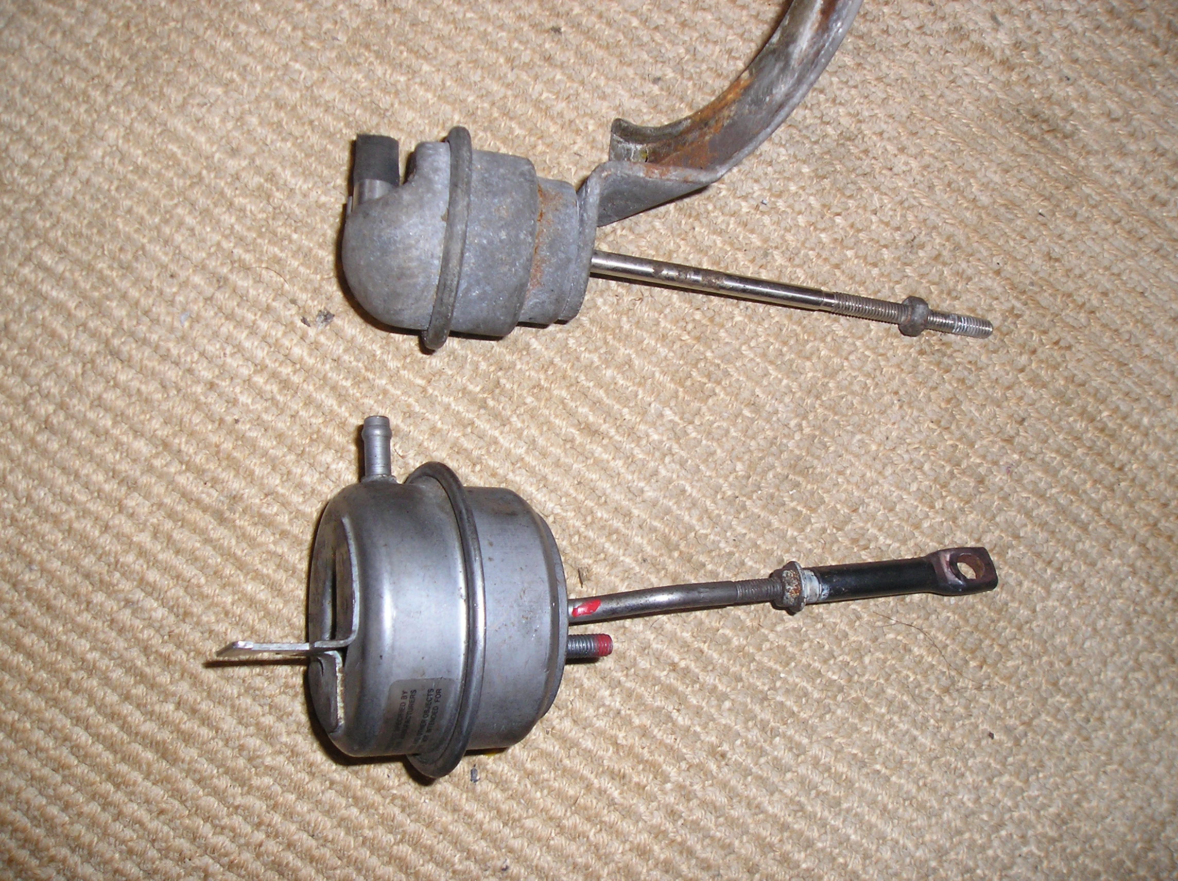
And this is how I propose to mount it onto the turbo

Can anyone see any problems with me getting it tack welded to the mani to hold it in place?
Posts: 4,883
Threads: 198
Joined: Jan 2012
Reputation:
135
Location: Not near you
Thanks: 0
Given 0 thank(s) in 0 post(s)
Well.. It's a cast mani, so there's a risk of shit welds fatiguing and the actuator falling off.
But my concern would be trying to fit that over the inlet mani. Don't know if it's the angle of the photo but it looks to be sitting right where the runner for cylinder 1 will be on the inlet mani..
Posts: 701
Threads: 59
Joined: Dec 2011
Reputation:
3
Location: Gillingham Kent
Car Model/Spec: 306 D-turbo
Thanks: 0
Given 0 thank(s) in 0 post(s)
Looking good mate do you need any help fitting the turbo I know that you are local to me.
Posts: 10,864
Threads: 117
Joined: Dec 2011
Reputation:
119
Location: Southampton
Car Model/Spec: 306 HDi and friends
Thanks: 13
Given 106 thank(s) in 106 post(s)
Having looked at another xud thread i can see that is the way the turbo is meant to sit, so i'll shush lol. What Pellowe said, that's what i meant about it looking upside-down (ie it sticks too far "up), I just did a bloody awful job of explaining it.
Posts: 1,070
Threads: 115
Joined: Oct 2012
Thanks: 0
Given 0 thank(s) in 0 post(s)
06-10-2013, 06:34 AM
(This post was last modified: 06-10-2013, 07:17 AM by 306Puggy.)
(05-10-2013, 09:05 PM)cwspellowe Wrote: Well.. It's a cast mani, so there's a risk of shit welds fatiguing and the actuator falling off.
But my concern would be trying to fit that over the inlet mani. Don't know if it's the angle of the photo but it looks to be sitting right where the runner for cylinder 1 will be on the inlet mani..
Ah, yes! See what I mean about not thinking of things until someone points it out! I totally forgot all about the inlet mani when I was visualising how this would fit  Well, for the moment I will crack on with the other bits like testing the actuator and the inlet piping. Does anyone know if I can use the existing inlet piping that goes onto the standard turbo? Would save time and money if I could.
(06-10-2013, 12:52 AM)Jtrigga Wrote: Looking good mate do you need any help fitting the turbo I know that you are local to me.
Heh, thanks Jtrigga, I know we have stepped on each other's toes in the past, thanks for extending an olive branch  Let's see what happens with the driveway issue, I'll let you know bud.
(06-10-2013, 05:44 AM)Poodle Wrote: Having looked at another xud thread i can see that is the way the turbo is meant to sit, so i'll shush lol. What Pellowe said, that's what i meant about it looking upside-down (ie it sticks too far "up), I just did a bloody awful job of explaining it.
Heh, okay. Yeah, the XUDs do look weird because of the angle they sit at.
Right so just to reiterate, the jobs that I can be getting on with are:
Testing actuator
Sorting the inlet ducting and (hopefully) using the standard inlet ducting
And I have just remembered, Dave has gone travelling I believe? So it looks like I'll have to sort out the actuator on my own. This is so hard without an engine to mock it up to!
Edit: What do we think about having the actuator down here?
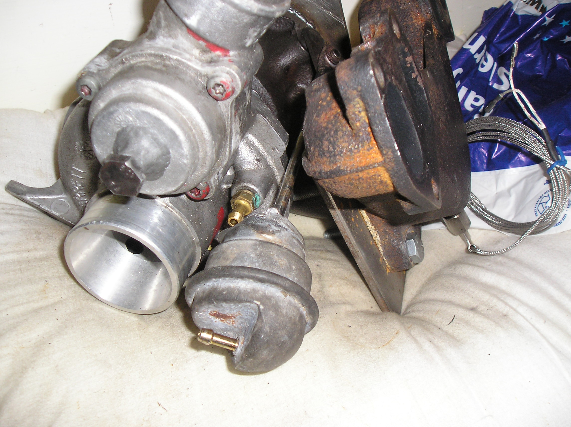
Posts: 4,660
Threads: 343
Joined: Jul 2012
Reputation:
15
Location: Chesterfield
Car Model/Spec: 106 gti / 306 hdi estate
Thanks: 4
Given 3 thank(s) in 3 post(s)
Why dont you lift it up and use the 2 screws on the valve thingy (what ever it is) on the out let to hold it? if you make a bracket of course but that seems the easiest way to me as were you have it now i struggle to see how you can keep it in place?
Posts: 1,070
Threads: 115
Joined: Oct 2012
Thanks: 0
Given 0 thank(s) in 0 post(s)
Hi Chris_90. The issue with having it at that height is that it would be in the way of the inlet manifold. Keeping it in place isn't too much of a problem because I have off cuts of metal I can use to weld to the adapter plate and then get the actuator welded to the other end.
At the moment we are just trying to find a location for the actuator that won't be in the way of anything round the back of the engine. Obviously I don't have an engine to mock it up on or it would be way easier to do, hence why I have to show a picture to the forum and then get the forum to say whether it is okay or not 
Posts: 4,660
Threads: 343
Joined: Jul 2012
Reputation:
15
Location: Chesterfield
Car Model/Spec: 106 gti / 306 hdi estate
Thanks: 4
Given 3 thank(s) in 3 post(s)
Ahhhh been a while since i looked down back of a d turbo, are you not gonna struggle with clearance of the valve thing you have sealed off?
Think welding a bracket to the adapter plate is best idea if its gotta be down there out of the way.
Posts: 1,070
Threads: 115
Joined: Oct 2012
Thanks: 0
Given 0 thank(s) in 0 post(s)
Right, this update was supposed to be this morning, but due to internet shenanigans I haven't been able to post it:
I don't know about the recirc valve yet Chris_90, but I can hacksaw the head of the bolt off if need be, if I have to go any further then I will need to make up a flat blank off plate for it.
I just need to wait for a Dturbo person to confirm whether the actuator being down there is "out of the way" or not, before I get a bracket welded for it 
Anyway, another minor update (already, I hear you cry?)
Trimmed the adapter plate right down so that it doesn't obstruct the wastegate arm and removed some other unnecessary bits, reckoned I saved a few hundred grams on it

Then I realised that the actuator can be extended even further out if need be
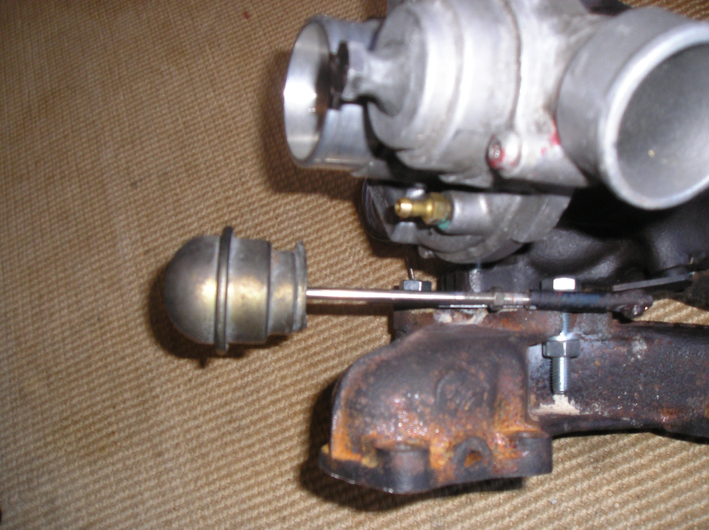
Then I removed the comp housing and hacksawed off the old actuator bracket, it's already gonna be a tight fit down the back of the lump without that huge bracket sticking out!
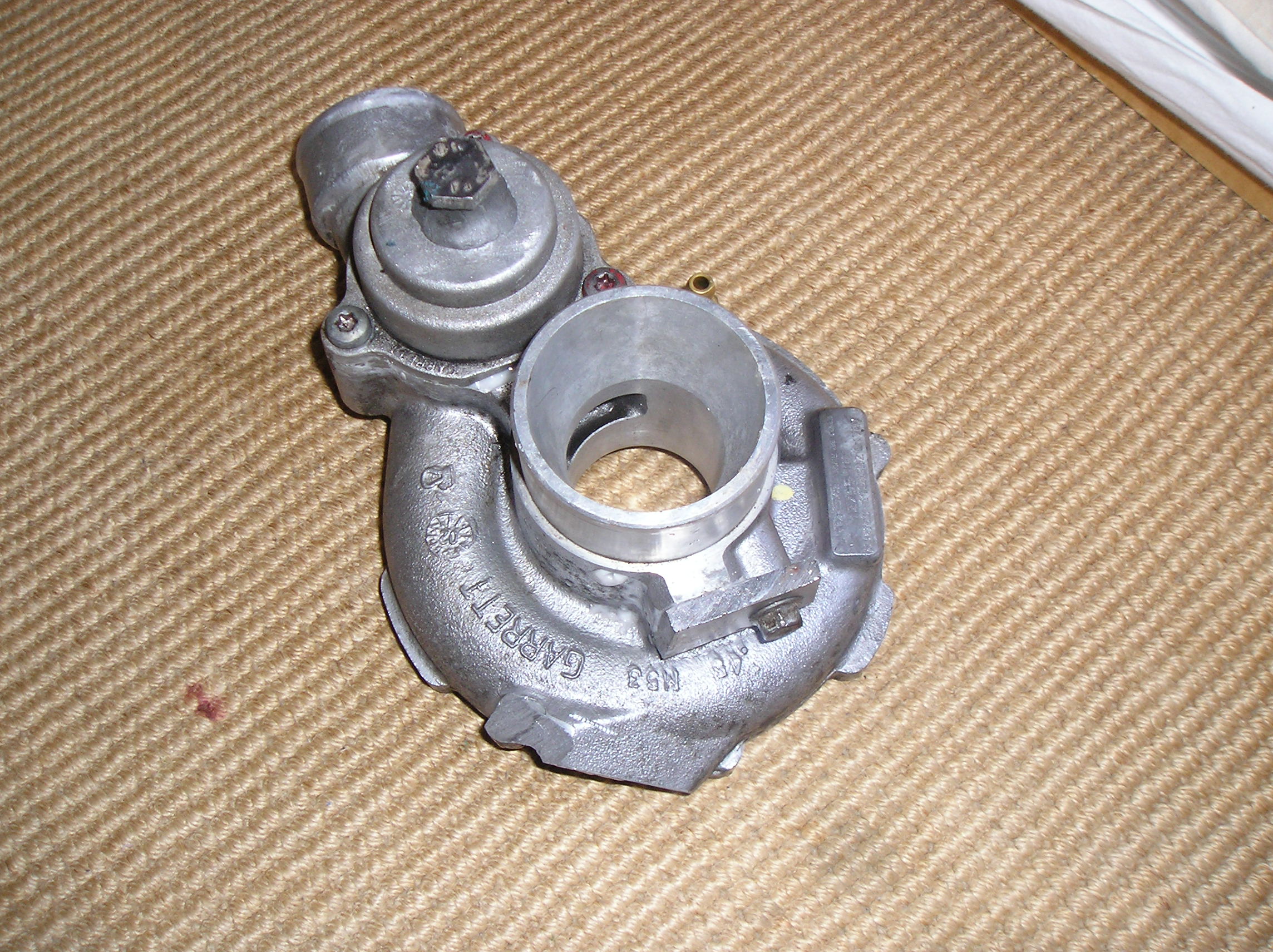
So yeah, at the moment the main thing I am waiting on is advice on this actuator!  Welding is annoyingly permanent when it's in the wrong spot.
Posts: 345
Threads: 35
Joined: Dec 2011
Reputation:
3
Location: Preston
Thanks: 0
Given 1 thank(s) in 1 post(s)
06-10-2013, 04:48 PM
(This post was last modified: 06-10-2013, 04:49 PM by martyn92.)
This is mine on the td04 and used a different manifold so spacing may be a little different.
May be of help?
![[Image: 20130821_171549_zps2240a2b1.jpg]](http://i799.photobucket.com/albums/yy275/martyn992/20130821_171549_zps2240a2b1.jpg)
![[Image: 20130821_171610_zps530cfb5e.jpg]](http://i799.photobucket.com/albums/yy275/martyn992/20130821_171610_zps530cfb5e.jpg)
![[Image: 65613_10200761612710317_1548698655_n_zps68c27004.jpg]](http://i799.photobucket.com/albums/yy275/martyn992/65613_10200761612710317_1548698655_n_zps68c27004.jpg)
CONVOI EXCEPTIONNEL
Posts: 1,070
Threads: 115
Joined: Oct 2012
Thanks: 0
Given 0 thank(s) in 0 post(s)
06-10-2013, 05:11 PM
(This post was last modified: 06-10-2013, 05:12 PM by 306Puggy.)
Looks like there's plenty of space off to the side there  Plus my actuator is about 2/3rds of the size as well...looks like I've got to try it and see, unless anyone else wants to chime in at the last minute...nope? Okay, or forever hold your piss  So plans will go ahead to get the wastegate actuator welded on the front of the turbo just behind the exhaust mani then.
Posts: 345
Threads: 35
Joined: Dec 2011
Reputation:
3
Location: Preston
Thanks: 0
Given 1 thank(s) in 1 post(s)
Dont look at me if it goes wrong! 
![[Image: 65613_10200761612710317_1548698655_n_zps68c27004.jpg]](http://i799.photobucket.com/albums/yy275/martyn992/65613_10200761612710317_1548698655_n_zps68c27004.jpg)
CONVOI EXCEPTIONNEL
Posts: 1,070
Threads: 115
Joined: Oct 2012
Thanks: 0
Given 0 thank(s) in 0 post(s)
I will be looking squarely and directly at you...no just kidding. I want some input from others first before I get this bracket made up. I'll try to be as annoying as possible and keep bumping the thread until someone says something 
Posts: 1,804
Threads: 129
Joined: Mar 2012
Reputation:
11
Thanks: 0
Given 0 thank(s) in 0 post(s)
06-10-2013, 05:22 PM
(This post was last modified: 06-10-2013, 05:22 PM by strictly_perv.)
This is one of my old K04 when I was testing it on an engine but by the looks you should have plenty of room
![[Image: IMAG0856.jpg]](http://i834.photobucket.com/albums/zz263/max_tait/IMAG0856.jpg)
Stage 2 XUD Sedan
Posts: 20,092
Threads: 591
Joined: Nov 2012
Reputation:
54
Location: Cotswolds
Car Model/Spec: Stage 13 16v HDi


Thanks: 22
Given 68 thank(s) in 68 post(s)
thats flippin kock eyed dude!
Posts: 1,804
Threads: 129
Joined: Mar 2012
Reputation:
11
Thanks: 0
Given 0 thank(s) in 0 post(s)
Hence the mole grips....
Stage 2 XUD Sedan
Posts: 1,070
Threads: 115
Joined: Oct 2012
Thanks: 0
Given 0 thank(s) in 0 post(s)
Plenty of room eh? I like the sound of that  Well, just ordered a bicycle foot pump off eGay this morning, so assuming that arrives by Wednesday I should be able to test the actuators and compare them and then get the actuator bracket welded! Also I just remembered obviously using a 6mm adapter plate there is gonna be 6mm more room at the front anyway! So hopefully that will leave loads of space for the actuator. But I am referring to the original position that I showed you, not the one where it is fully wound out on the control arm, just to clarify.
Posts: 1,070
Threads: 115
Joined: Oct 2012
Thanks: 0
Given 0 thank(s) in 0 post(s)
Right, another update. Pump arrived in the post today. Tested both actuators and me being me didn't think about the fact that the pump I bought being a cheapo one didn't have much resolution on the pressure gauge at all. Basically it starts at about 20 psi so all I know is that both actuators work and they are all fully extended by 20 psi by about 1.5 cm each.
So they are both pretty much comparable and as I am going to be running an MBC so I guess the pressure doesn't matter at all, it would only be if they didn't move until 30 psi or something that I would be in the shit because I will be running 25 psi max on this setup.
However, I have tested the wastegate arm and it appears to have about 4 centimetres of travel from fully shut to fully open? Or is most of that just redundant travel? Because as said the actuator arms only seem to move about 1.5cm each.
Right, pictures of testing below:
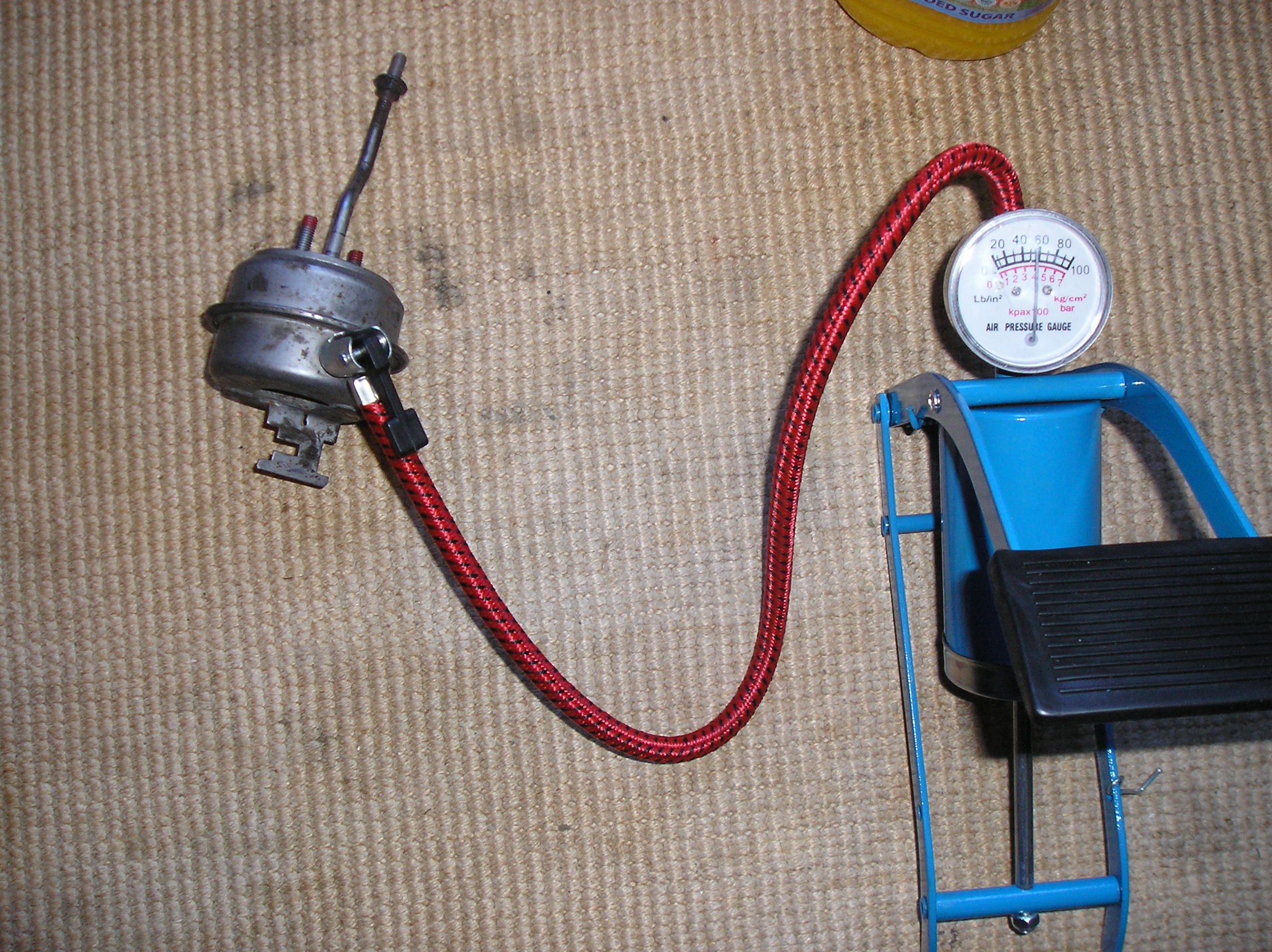

Next thing to do is to get a bracket welded up and sort out the exhaust elbow.
Posts: 345
Threads: 35
Joined: Dec 2011
Reputation:
3
Location: Preston
Thanks: 0
Given 1 thank(s) in 1 post(s)
The wastegate only needs to open a little 
![[Image: 65613_10200761612710317_1548698655_n_zps68c27004.jpg]](http://i799.photobucket.com/albums/yy275/martyn992/65613_10200761612710317_1548698655_n_zps68c27004.jpg)
CONVOI EXCEPTIONNEL
Posts: 1,070
Threads: 115
Joined: Oct 2012
Thanks: 0
Given 0 thank(s) in 0 post(s)
14-10-2013, 02:37 PM
(This post was last modified: 14-10-2013, 02:38 PM by 306Puggy.)
Right, quick update, got an elbow for a bargain. It was up on eGay for 25 quid but knocked him down to 20 for it, bargain!
Here's the beauty in question:
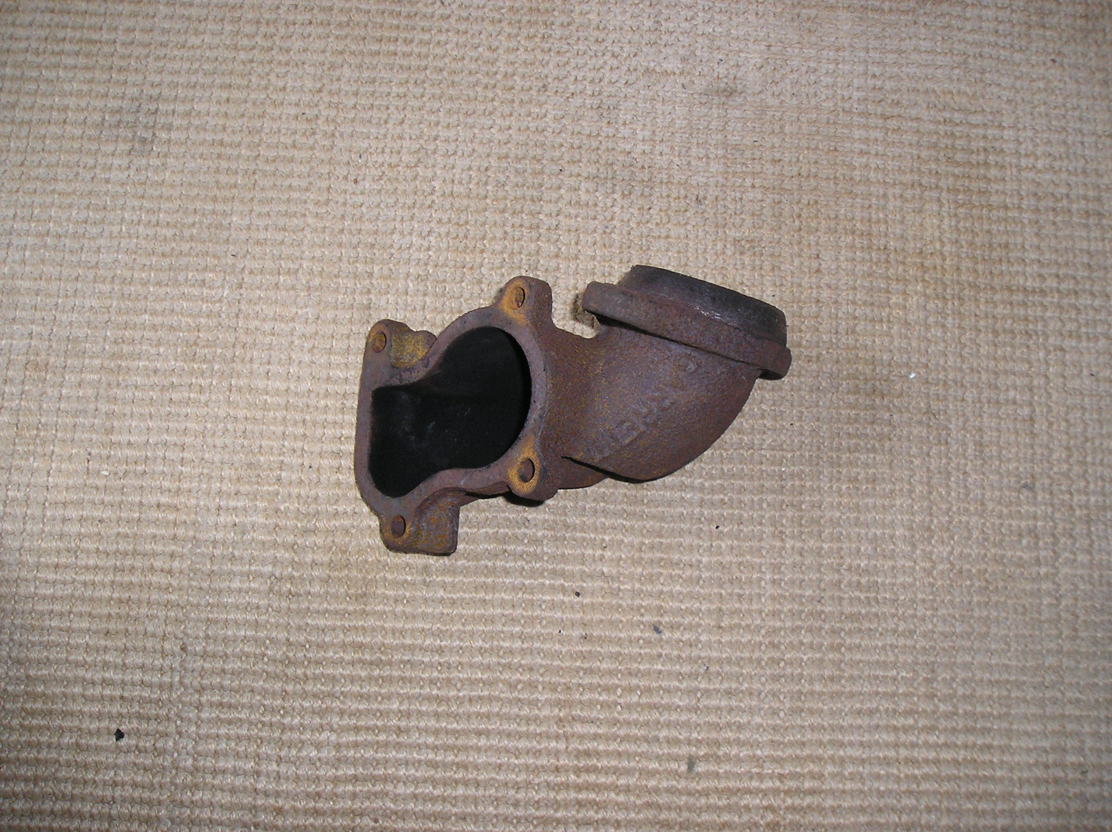
It is a T2 elbow, and it's really restrictive, a lot more so than the K14 one! Good thing I am only using the flange off it really then isn't it?
Next stage is to get a mandrel bent 3" pipe like the cheaper one of the two I showed you all in this thread:
http://306oc.co.uk/forum/thread-16999.html
After that get the reducer and get the flange welded to the reducer then get the reducer welded to the flange!
Oh and I did some working out of the angle for the elbow last week as well, but didn't post it as it was a bit off topic from actuator testing:
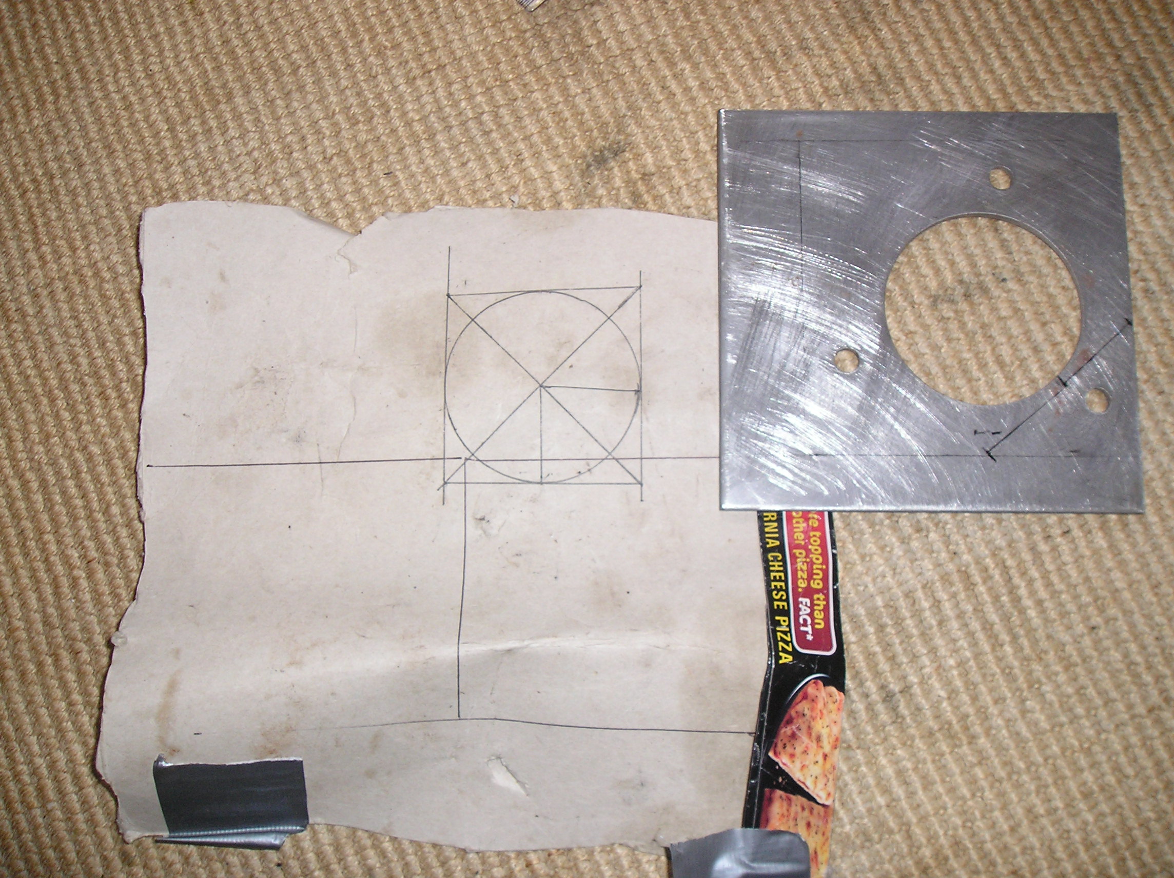
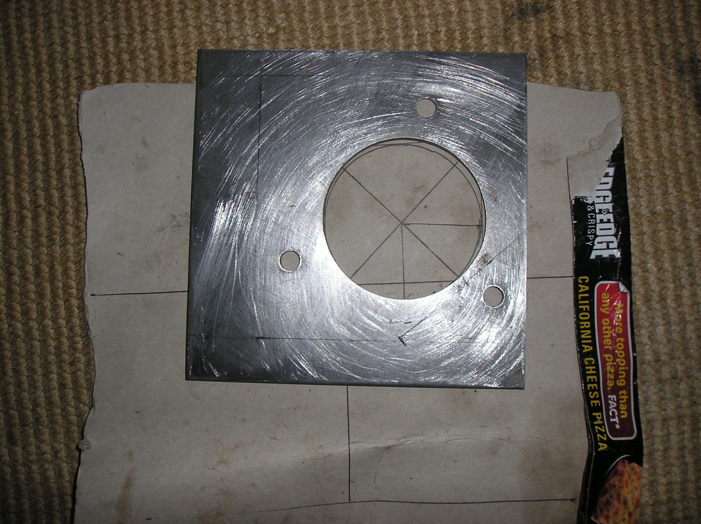

And that, my friends, is how you work out a 45 degree angle on a circle! Saves a fortune on V band clamps. If anyone needs this described in detail just PM me 
Posts: 3,662
Threads: 127
Joined: Feb 2012
Reputation:
33
Location: London
Car Model/Spec: ZX Volcane TD
Thanks: 6
Given 32 thank(s) in 32 post(s)
Please tell me you haven't spent £20 on a T2 elbow - just so you can cut the flange off it and weld that to a reducer and then to a 3inch 90?
Posts: 6,482
Threads: 226
Joined: Dec 2011
Reputation:
24
Location: Cornwall
Car Model/Spec: A3 TDi
Thanks: 0
Given 0 thank(s) in 0 post(s)
You spent 20quid on that piece of crap? Could of bought a tight radius 90, flexi and maybe a reducer aswell for that!
Doesnt even own a 306.
Posts: 15,646
Threads: 541
Joined: Dec 2011
Reputation:
124
Location: Aylesbury
Car Model/Spec: 320bhp Impreza WRX
Thanks: 7
Given 59 thank(s) in 58 post(s)
(14-10-2013, 02:56 PM)Tom Wrote: You spent 20quid on that piece of crap? Could of bought a tight radius 90, flexi and maybe a reducer aswell for that! You couldn't, not in 3" at least.
|


![[Image: signature_zps1a02ba79.jpg]](http://i1128.photobucket.com/albums/m481/martypellowe/signature_zps1a02ba79.jpg)
 Well, for the moment I will crack on with the other bits like testing the actuator and the inlet piping. Does anyone know if I can use the existing inlet piping that goes onto the standard turbo? Would save time and money if I could.
 Let's see what happens with the driveway issue, I'll let you know bud.
 Welding is annoyingly permanent when it's in the wrong spot.
![[Image: 20130821_171549_zps2240a2b1.jpg]](http://i799.photobucket.com/albums/yy275/martyn992/20130821_171549_zps2240a2b1.jpg)
![[Image: 20130821_171610_zps530cfb5e.jpg]](http://i799.photobucket.com/albums/yy275/martyn992/20130821_171610_zps530cfb5e.jpg)
![[Image: 65613_10200761612710317_1548698655_n_zps68c27004.jpg]](http://i799.photobucket.com/albums/yy275/martyn992/65613_10200761612710317_1548698655_n_zps68c27004.jpg)

![[Image: IMAG0856.jpg]](http://i834.photobucket.com/albums/zz263/max_tait/IMAG0856.jpg)